Details of awards received by the Signpost are here.
All contents copyright © 2000-2006 Readout Publications |
The Read-Out Instrumentation Signpost Measurement, Control and Automation Resources throughout the World
HOW FIELDBUS WORKS - an easy to read background note from Moore Industries
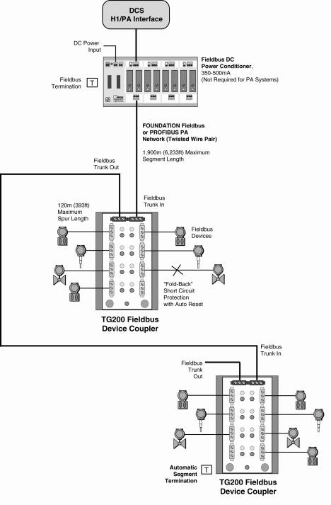
A fieldbus segment - FOUNDATION fieldbus or PROFIBUS - is a single twisted pair wire carrying a digital signal and power that connects multiple fieldbus devices, such as temperature, flow, level and pressure transmitters, smart valves, actuators, and other instruments to a DCS or similar control system. FOUNDATION fieldbus can support up to 32 devices; PROFIBUS PA can have up to 128 "slaves."
The fieldbus segment begins at an interface device at the control system. On a FOUNDATION fieldbus system, the interface is called an H1 interface; on a PROFIBUS system, it is a PROFIBUS DP/PA segment coupler. In terms of signal wiring and power requirements, FOUNDATION fieldbus H1 and PROFIBUS PA are identical.
Each segment is driven by a power conditioner that provides 350-500mA at up to 32 V over a 1,900m distance. Each fieldbus device typically requires 10-30mA, but some devices can draw more current. Generally, power conditioners are used in redundant pairs for an entire segment.
Each fieldbus device connects via a "drop" on the fieldbus segment. The simplest connection is a "T." The problem with a "T" connection is that if any one of the devices short out, it takes down the entire segment.
Another way to connect fieldbus devices is via fieldbus junction boxes, often referred to as "device couplers" - such as MooreHawke's TG200 TRUNKGUARDÅ - that allow multiple fieldbus devices to connect at one time. Typically, users will install a device coupler in a field enclosure, and connect multiple instruments to it. The fieldbus cable may continue onward to another device coupler. A 32-instrument segment may have one or more device couplers.
The advantage of a coupler is that each device connects via a "spur" - like a "T," but with protection against shorts. If a fieldbus device shorts, only that spur is affected.
Other fieldbus couplers use a "current-limiting" technique, which holds a fault on the segment; this adds up to 60mA of current per fault, deprives other instruments on the segment of power, overloads the segment power supply, and can cause catastrophic failures on the segment. The new TG200 from Moore Industries uses a "fold-back" technique which disconnects the shorted spur from the segment, thus preventing loss of an entire segment.
Historically, users have been wary of relying on "current limiting" couplers, and limited each segment to only 16 devices to prevent large-scale segment failures. With TG200 couplers, users no longer have to worry about such failures and can have more confidence about placing more devices on their FOUNDATION fieldbus and PROFIBUS segments. Since the cost of H1 cards ($2,500) can be cost prohibitive, allowing users to place more devices on a segment can save users a considerable amount.
Every fieldbus segment should be terminated at both ends for proper communication. If a segment is not terminated properly, communications errors from signal reflections may occur. A frequent commissioning problem during startup is determining that terminators are correctly located. Most device couplers use manual on/off DIP switches to terminate couplers. During installation of the fieldbus system, the DIP termination switches sometimes are set incorrectly, creating problems during startup. The instruments can behave erratically, drop off the segment mysteriously, and generally raise havoc - all because the terminations are not set properly. With the TG200's Automatic Segment Termination feature, these problems are eliminated, allowing commissioning and start-up timescales to be drastically reduced.
|
|


 Fieldbus links on this site.